Msd 3 Step Module Wiring Diagram
Msd 8737 Rpm Module Selector Installation Instructions Jegs
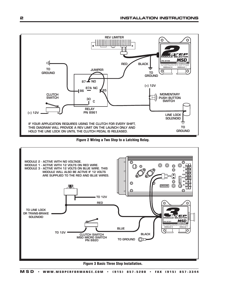
2installation Instructions M S D Figure 3 Basic Three Step Installation Figure 2 Wiring A Two Step To A Latching Relay Msd 8739 Two Step Module Selector Installation User Manual Page 2 4 Original Mode
Installation Instructions 3 M S D Msd 8739 Two Step Module Selector Installation User Manual Page 3 4 Original Mode
Msd 8737 Three Step Module Selector Installation Manuals

Fe 7485 Msd 6al Ignition Wiring Ignition Wiring Diagram Msd 6al Ignition Wiring Diagram

Msd Digital 6 Wiring Diagram Valid Msd Hei Distributor Wiring Diagram Msd Wire

To lengthen the wires use one size bigger gauge wire 12 gauge for.
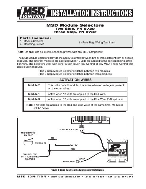
Msd 3 step module wiring diagram. Page 1 msd module selectors two step pn 8739 three step pn 8737 parts included. Collection of msd digital 6al wiring diagram. Find msd three step module selectors 8737. This one is for the analog 6al box that s older.
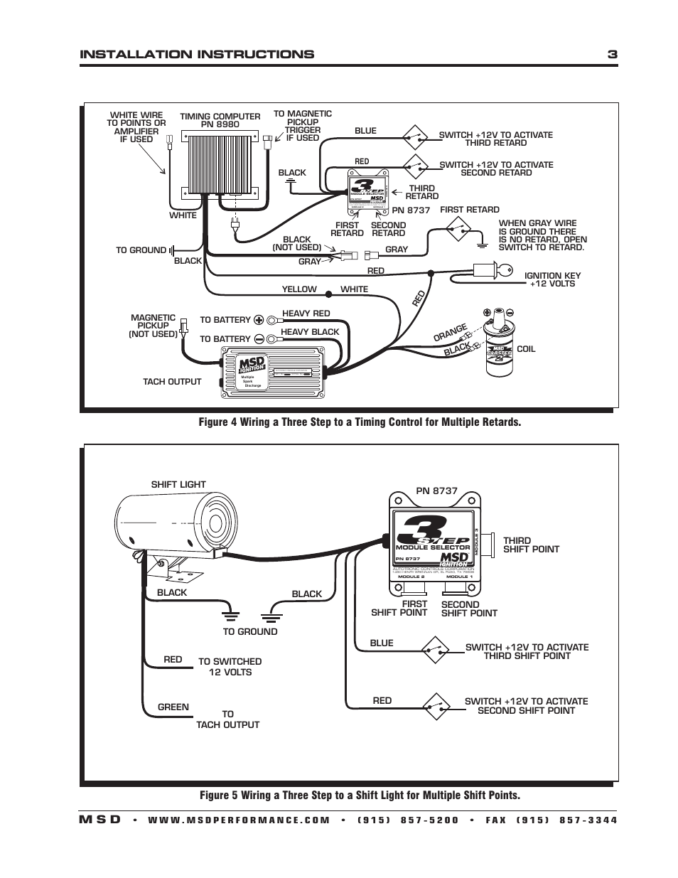
When activated the timing is retarded 25. This helps keep tire temperatures consistent. They feature three built in rev limiters one for burnout one for starting line launch and one for high end. It shows the components of the circuit as simplified shapes and also the power as well as signal connections in between the tools.
Mounting wiring msd 8732 2 step rev control for digital 6al 8739 diagram e29 installation instructions 3 m s d two module how to install a launch master limiter on 2011 and rx7club com mazda rx7 help 6010 ls1tech camaro firebird selector manuals line lock question clutch switch mustang forums trans brake smooth stage performancetrucks net mounting wiring read more. Page 2 installation instructions rev limiter step module selector pn 8739 black autotronic controls corporation 1490 henry brennan dr el paso tx 79936 module 2 module 1. Module 3 active with 12 volts on blue wire. 4 installation instructions s uêwwwmsdperformance comê uê x ê nxx ç óî ê uê 8 ê x ê nxç îî wiring general wiring information wire length.
The different rpm modules are activated when 12 volts are applied to a corresponding wire. When the line lock button is released. A wiring diagram is a simplified standard pictorial representation of an electrical circuit. As an example we ll use a drag car with a three step module selec tor plugged into the rpm socket of a 7al 2 ignition.
Do not use solid core spark plug wires with any msd component. Module 1 active with 12 volts on red wire. Msd 3 step module selectors are designed for great versatility. These selectors use the msd plug in rpm modules.
Figure 3 basic three step installation. Find msd three step module selectors 8737 and get free shipping on orders over 99 at summit racing. Start retard the start retard of the 7al 3 is designed to ease starting on engines with locked timing high compression and a lot of advance. Follow me on s.
Here is the install of the msd 3 step. To 12v clutch switch msd micro switch pn. Installation instructions optional wiring this wiring section details the optional features of the msd 7al 3 and how to wire each system. Msd two step wiring diagram wiring diagram is a simplified usual pictorial representation of an electrical circuit it shows the components of the circuit as simplified shapes and the talent and signal friends amongst the devices.
T a c h c c ign pts m m ground rpm to ground to 12v module 2 active with no voltage. All of the wires of the msd ignition may be shortened as long as quality connectors are used or soldered in place. This module will also be active if 12 volts are supplied to the red and blue wires.

Basic Hot Rod Engine Hei Wiring Diagram And How To Install Msd Al Ignition Box On Hei In 2020 Msd Hot Rods Ignite

Fs 5785 Msd 3 Step Wiring Diagram Wiring Diagram

Image Result For Gm Ignition Module Testing Coil Ignition Coil Ignite Coil

Chevy Ignition Coil Distributor Wiring Diagram In Addition Diagram Msd Automotive Care Automotive Illustration Diagram

Gm 4 Pin Hei Wiring Diagram Automotive Illustration Rod Coil

Pin On Msd Performance

Wiring Diagram For A Yamaha Warrior 350 And Electrical Diagram Motorcycle Wiring Diagram

How To Test The Gm Ignition Control Module 1995 2005 Auto Repair Car Mechanic Automotive Mechanic

Msd Ignition Power Grid System Controllers 77303 Free Shipping Grid System Power Grid System

Ad Ebay Msd Ignition 75591 Programmable Rpm Trans Shifter In 2020 Shifter Msd Transmission

Alkydigger Msd Ignition Timing Supercharger

Other Msd 8 Plus Ignition Box Pn 7805 Ignite Msd Ignition System

Pin By Richard Berry On 427 Cobra Boat Ladders The Row Cooler

Msd Ignition Heavy Duty Wire Pro Crimp Tool Ll 35051 Changeable Dies 3507 3510 Heavy Duty Crimps Ignite

New Dc Dc Converter 6 24v 12v 24v To 5v 3a Car Usb Charger For Phone Module Diy Using The Latest Usb Identification Circuit Storecharger

Pin On Deals Spark Plug Wires

Msd Atomic Efi Airforce Intake Manifold Black Gm Ls1 Ls6 Ls2 27023 Black Air Force Msd

Chevy 305 Engine Wiring Diagram And Engine Wiring Harness Diagram Wiring Library In 2020 Chevy C10 Chevy Truck Diagram
Https Encrypted Tbn0 Gstatic Com Images Q Tbn 3aand9gcs4zo4t7b6yazdt5wqgo3ptfdjqw Xnkwslq Hjwgsujkykcgti Usqp Cau

Msd Atomic Efi Airforce Intake Manifold Black Gm Ls1 Ls6 Ls2 27023 Black Air Force Msd

Holley 12 1200 Dominator In Line Billet Fuel Pump In 2020 Holley Performance Fuel Delivery Pumps

Reliance Controls 6 Circuit Power Transfer Switch Kit With Phone Out Alarm Transfer Switch Emergency Generator Generators For Sale

How To Build A 4l60e Transmission That Can Handle 1 000 Hp Custom Trucks Chevy Trucks Custom Truck Parts

Pin On Engines And Components Car And Truck Parts

Pin On Jig

Pin On Tire Accessories Wheels Tires And Parts Car And Truck Parts

Ub Machine 28 Long 3416 Threads Steel Suspension Tube Link Bar 422802apc Read More Reviews Of The Product By Visi Portable Ice Maker Steel Ice Maker Machine

Pin Ot Polzovatelya Dorothy Wilson Na Doske Estrellas

There Are Two Different Ecu Connectors For The 4l60e The Green Connector Is From 1999 2005 While 2006 And N Chevy Transmission Automotive Repair Transmission

Chevy 305 Engine Wiring Diagram And Engine Wiring Harness Diagram Wiring Library In 2020 Chevy C10 Chevy Truck Diagram
Reliance Controls 6 Circuit Power Transfer Switch Kit With Phone Out Alarm Transfer Switch Emergency Generator Generators For Sale

